How to Drive a 2.4″ ILI9341 TFT Display with ESP32
目录
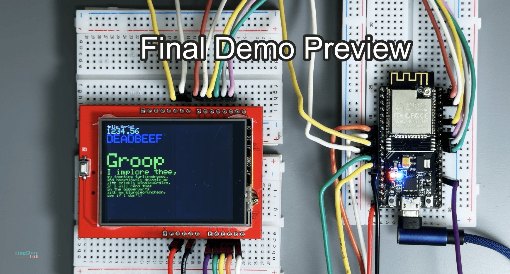
This guide walks you through driving an ILI9341 screen with an ESP32 using an 8-bit Parallel bus. Compared to the common SPI method, parallel mode offers a much higher refresh rate, making it perfect for dynamic graphics and animations.
Development Environment
- OS: MacOS
- Arduino IDE Version: 2.3.7
- ESP32 Board Version: 3.3.5 (Latest)
- TFT_eSPI Version: 2.5.43
Hardware Checklist (BOM)
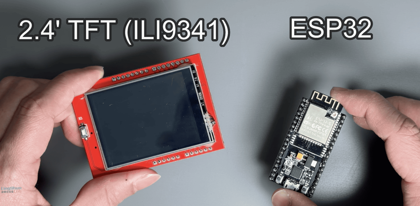
- ESP32 Dev Module x1
- 2.4 inch TFT display (ILI9341) x1
- Dupont wires (Jumper wires) xN
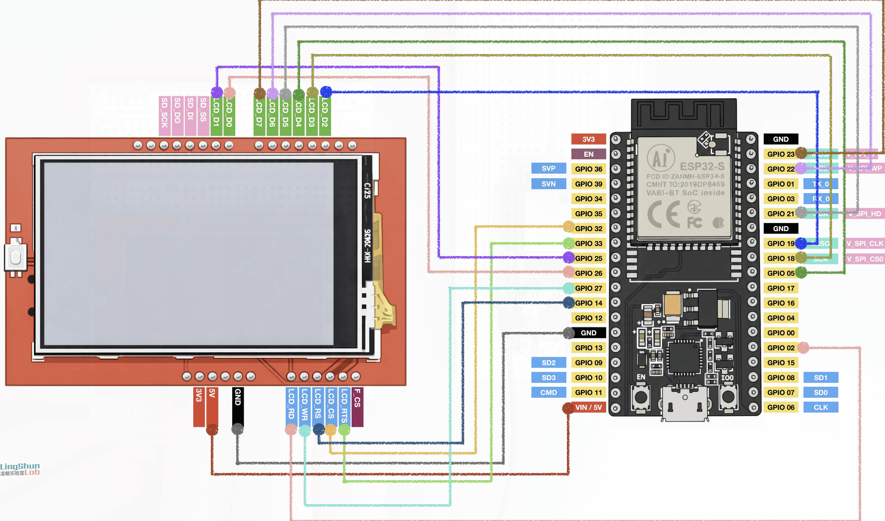
Wiring Guide
| TFT Pin | ESP32 Pin | Function |
|---|---|---|
| VCC (3V3/5V) | 3V3 / VIN | Power (Try 3.3V first) |
| GND | GND | Common Ground |
| LCD_D0 | GPIO 26 | Data Bit 0 |
| LCD_D1 | GPIO 25 | Data Bit 1 |
| LCD_D2 | GPIO 19 | Data Bit 2 |
| LCD_D3 | GPIO 18 | Data Bit 3 |
| LCD_D4 | GPIO 5 | Data Bit 4 |
| LCD_D5 | GPIO 21 | Data Bit 5 |
| LCD_D6 | GPIO 22 | Data Bit 6 |
| LCD_D7 | GPIO 23 | Data Bit 7 |
| LCD_CS | GPIO 32 | Chip Select |
| LCD_RTS | GPIO 33 | Reset |
| LCD_RS (DC) | GPIO 14 | Register Select (Data/Command) |
| LCD_WR | GPIO 27 | Write Control |
| LCD_RD | GPIO 2 | Read Control (Connect to 3.3V if not reading ID) |
Required Libraries
Arduino IDE Boards Manager: esp32
You need the official ESP32 board support by Espressif Systems. I am using the latest version here.
Arduino IDE Library Manager: TFT_eSPI
Search for and install the TFT_eSPI library (by Bodmer).
Configuring User_Setup.h
TFT_eSPI is a fantastic library, but getting the pin definitions right is crucial. All configurations for the driver, board, and pins are handled in the User_Setup.h file.
File Location:
Documents > Arduino > libraries > TFT_eSPI > User_Setup.h
Action: Open the file, clear all existing content, and copy-paste the code below. I've optimized this specifically for the ESP32 parallel setup.
// =========================================================================
//   User_Setup.h - Display driver configuration file for TFT_eSPI library
//
//   Hardware: ESP32 (No PSRAM or not using GPIO 16/17)
//   Driver: ILI9341 (8-bit parallel mode)
// =========================================================================

// -------------------------------------------------------------------------
// 1. Driver Type Definition
// -------------------------------------------------------------------------
#define ILI9341_DRIVER       // Generic ILI9341 Driver

// -------------------------------------------------------------------------
// 2. Color Order Definition
// -------------------------------------------------------------------------
// If colors are inverted (e.g., red becomes blue), change this.
#define TFT_RGB_ORDER TFT_BGR  // Most ILI9341 screens use BGR order
// #define TFT_RGB_ORDER TFT_RGB

// -------------------------------------------------------------------------
// 3. Screen Resolution
// -------------------------------------------------------------------------
#define TFT_WIDTH  240
#define TFT_HEIGHT 320

// -------------------------------------------------------------------------
// 4. Interface Configuration (Critical)
// -------------------------------------------------------------------------
#define ESP32_PARALLEL       // Enable ESP32 parallel mode
#define TFT_PARALLEL_8_BIT   // Use 8-bit parallel bus

// -------------------------------------------------------------------------
// 5. Pin Definitions
// -------------------------------------------------------------------------

// --- Control Pins ---
// Optimization: CS/RST moved to GPIO 32+, keeping low GPIOs for data bus and WR.

#define TFT_CS   32  // Chip Select
#define TFT_RST  33  // Reset

// Data/Command selection - Must be in GPIO 0-31
#define TFT_DC   14

// Write signal - ★ Critical pin, must be in GPIO 0-31 and keep connections short
#define TFT_WR   27

// Read signal - If not reading screen data, can connect to 3.3V
#define TFT_RD    2

// --- Data Bus Pins D0 - D7 ---
// Must be within GPIO 0-31 range.
// Avoided GPIO 16, 17 (PSRAM/Flash) and 12 (Strap).

#define TFT_D0   26
#define TFT_D1   25
#define TFT_D2   19
#define TFT_D3   18
#define TFT_D4    5  // Note: GPIO 5 is a Strap pin, ensure screen does not pull it high during power-up
#define TFT_D5   21
#define TFT_D6   22
#define TFT_D7   23

// -------------------------------------------------------------------------
// 6. Backlight Control (Optional)
// -------------------------------------------------------------------------
// If your screen has a BLK or LED pin, connect it to an ESP32 pin and define it here.
// #define TFT_BL   4
// #define TFT_BACKLIGHT_ON HIGH

// -------------------------------------------------------------------------
// 7. Font Loading
// -------------------------------------------------------------------------
// Enable as needed; enabling more fonts consumes more Flash memory.

#define LOAD_GLCD   // Font 1. Original Glcd font
#define LOAD_FONT2  // Font 2. Small 16 pixel high font
#define LOAD_FONT4  // Font 4. Medium 26 pixel high font
#define LOAD_FONT6  // Font 6. Large 48 pixel font
#define LOAD_FONT7  // Font 7. 7 segment 48 pixel font
#define LOAD_FONT8  // Font 8. Large 75 pixel font
#define LOAD_GFXFF  // FreeFonts. Include access to the 48 Adafruit_GFX free fonts FF1 to FF48

#define SMOOTH_FONT // Enable smooth font loading

// -------------------------------------------------------------------------
// 8. Other Settings
// -------------------------------------------------------------------------
// In parallel mode, SPI frequency is usually ignored as speed is determined by CPU register write speed.
// Kept here for compatibility.
#define SPI_FREQUENCY       27000000
#define SPI_READ_FREQUENCY  20000000
#define SPI_TOUCH_FREQUENCY  2500000

// --- Touch Screen Settings ---
// If you use XPT2046 touch function (SPI interface).
// Warning: TFT_D6 is using GPIO 22 above. You'll need to reassign pins if using Touch.
// #define TOUCH_CS 22
Loading the Example Sketch
Open the following example to test your setup:
File -> Examples -> TFT_eSPI -> 320 x 240 -> TFT_graphicstest_one_lib
Compilation Error Fix (ESP32 Core 3.0+)
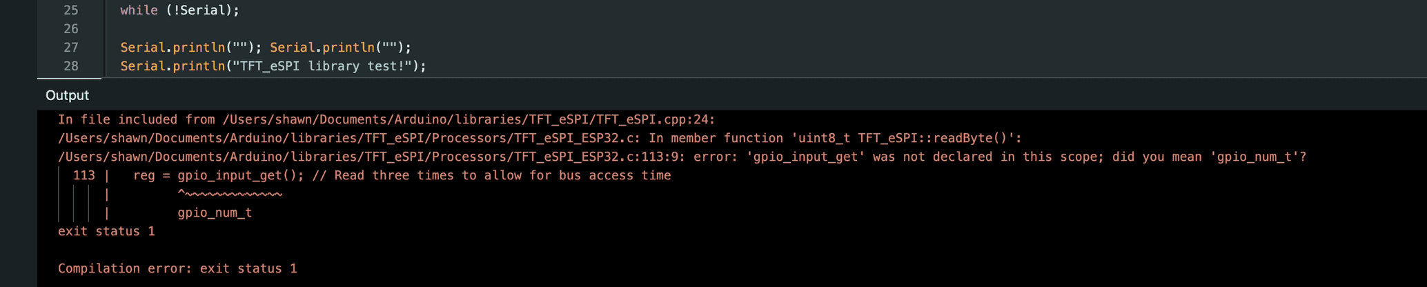
If your ESP32 board version is 3.0.0 or higher, you will likely hit this error when compiling:
error: 'gpio_input_get' was not declared in this scope; did you mean 'gpio_num_t'?Why is this happening?
The gpio_input_get() function was part of the older ESP-IDF framework. In the recent ESP32 Arduino Core 3.0.x update, Espressif refactored the low-level APIs, removing this function. The current TFT_eSPI library hasn't been fully updated to match this change yet.
The Fix
You could downgrade your board version to 2.0.x, but the better solution is to patch the library manually.
- Locate and open this file:
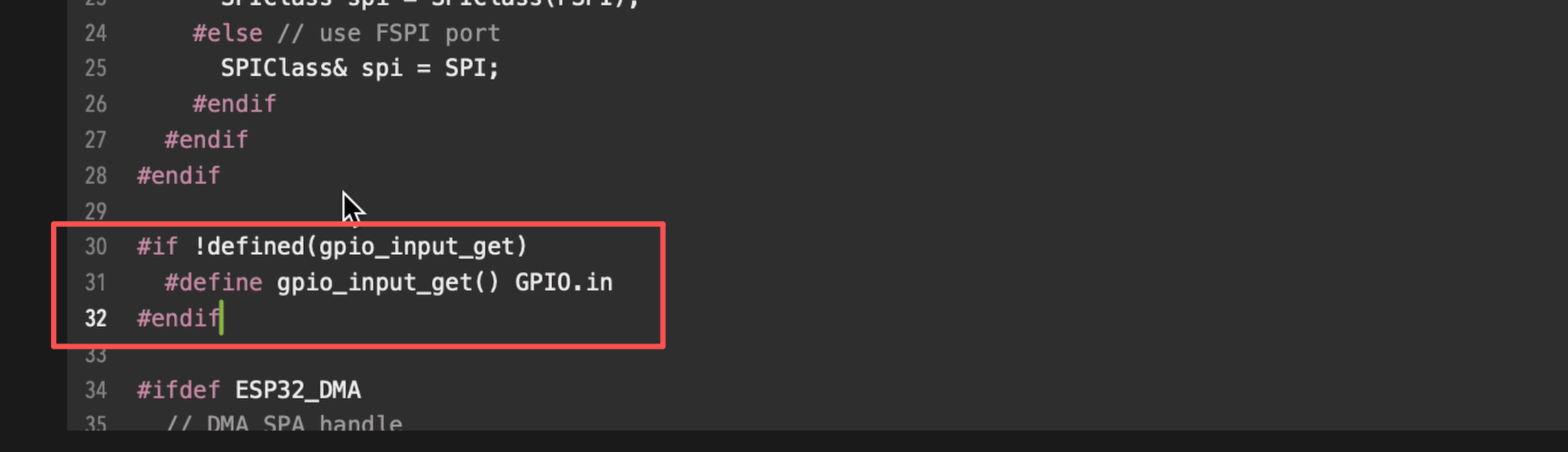
Documents/Arduino/libraries/TFT_eSPI/Processors/TFT_eSPI_ESP32.c - Add the following macro definition at the very top of the code:
#if !defined(gpio_input_get)
  #define gpio_input_get() GPIO.in
#endif
Save the file and you're good to go.
Fixing Mirrored/Reversed Text
Compilation passed, upload complete, and the screen is on. But don't celebrate just yet—if you look closely, the text might be mirrored (displayed backwards).
To fix this, we need to find the correct rotation setting. Modify the loop() function in the example sketch (around line 102) to cycle through rotation modes 4 to 7:
void loop(void) {
  for (uint8_t rotation = 4; rotation < 8; rotation++) {
    tft.setRotation(rotation);
    testText();
    delay(2000);
  }
}
Upload this code. Watch the screen, note which rotation number displays the text correctly, and use that number in your future setup() code (e.g., tft.setRotation(4);).
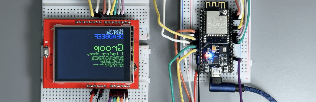
Final Result
Once you've set the correct rotation, your 2.4-inch ILI9341 screen should be running perfectly. Congratulations!
Troubleshooting (FAQ)
Here are some common issues and quick fixes.
Q1: The screen lights up white, but shows no image?
- A1: 90% of the time, this is because parallel mode isn't enabled. Double-check
User_Setup.hand ensure#define ESP32_PARALLELis uncommented. - A2: Check the TFT_RST (GPIO 33) connection. If the screen doesn't reset, it won't initialize.
Q2: Colors are wrong (e.g., Red looks Blue)?
- A: This is an RGB vs BGR definition issue. Go to
User_Setup.hand swap the setting. If it's#define TFT_RGB_ORDER TFT_RGB, change it to#define TFT_RGB_ORDER TFT_BGR.
Q3: Does this setup support Touch?
- A: This guide covers the display driver only. These screens usually come with an XPT2046 touch chip, which uses a separate SPI interface. You will need to wire the touch pins (T_CLK, T_CS, T_DIN, T_DO, T_IRQ) separately and enable
TOUCH_CSin the setup file. Warning: You cannot share the touch pins with the parallel data pins (D0-D7).
Q4: Why not just use the standard VSPI/HSPI driver?
- A: Speed. The 8-bit parallel driver is significantly faster than SPI, making it much better for high-FPS interfaces or retro gaming emulation.

")
")